
Items : %s%s
VSC7514XKS
VSC7514XKS
536-VSC7514XKS
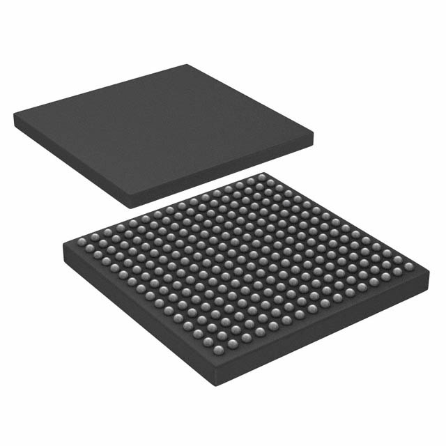
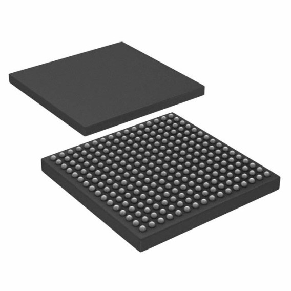
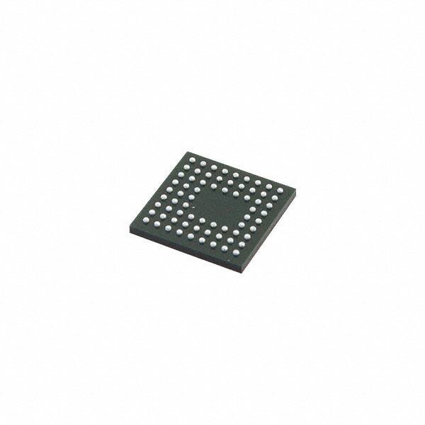
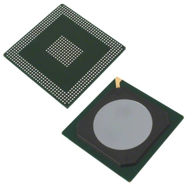
256-BGA
256 Termination 1mm Analog Switch Ocelot?-10 Series 1V 256-BGA
In Stock : 2245
Share
Please send RFQ, we will respond immediately.


Product Details
Purchasing and Inquiry
VSC7514XKS Overview
It is employed in the way of {0} package.In the {0} package, it is used.It is used as part of the {0} package.It is employed in the way of the {0} package in order to perform its functions.A package called {0} uses it to implement this functionality.An example of its use is in the {0} package.It is used in conjunction with the package {0}.It takes advantage of the {0} package to perform its functions.In order to perform its functions, it utilizes the {0} package.In order to perform its functions, it is employed in the same way as the {0} package.{0} is the recommended mounting type for this part.The recommended mounting type for this part is {0}.This part should be mounted as {0}.It is recommended to mount this part using type {0}.Mounting type {0} is recommended.This part is best mounted with type {0}.A {0} mounting type is recommended for this part.A mounting type of {0} is recommended.For this part, {0} is the recommended mounting type.This part should be mounted with the {0} mounting type.The device has {0} channels on it.{0} channels are available on the device.It has {0} channels.{0} channels are present on the device.In this device, there are {0} channels.{0} channels are on the device.As far as the device is concerned, it has {0} channels.It has a total of {0} channels on it.It appears that the device has only {0} channels available to it.The device has a channel count of {0}.The device is contained within the {0} package.The {0} package contains the device.{0} is the package containing the device.This device is enclosed in the package {0}.{0} is the package that contains the device.{0} is the package in which the device is contained.This device is packaged in {0}.This device can be found within the package {0} which contains the device.Embedded within the {0} package is the device.In the package {0} is the device.It is suitable for a wide range of applications, including {0}.There are a wide variety of applications for it, including {0}.There are many possible applications for it, including {0}.With its versatility and wide range of applications, it is suitable for a wide range of purposes, including {0}.There is a wide variety of applications for which it is suitable, including (0).As a result, it can be used in any number of different applications, including {0}.With its features, it can be used in a wide range of applications, such as {0}.In terms of applications, it is for a wide range of fields, including {0}.It can be applied to a wide range of applications, including {0}.There are a variety of applications for it, including {0}.It varies the range of {0} operating temperature.The range of {0} operating temperatures can be varied.Variations are made to the {0} operating temperature range.Depending on the operating temperature, it varies the range of {0}.A variable range {0} of operating temperatures is provided.Temperatures are varied in the {0} operating range.Depending on the setting, the operating temperature at {0} can be varied.Temperatures can be controlled at {0} according to the setting.It is possible to set the temperature to {0} according to the setting.Depending on the settings, temperatures can be controlled at {0}.The number of terminations on the chip is {0}.There are {0} terminations on the chip.This chip has {0} terminations.{0} terminations are present on the chip.{0} is the number of terminations on the chip.It has {0} terminations.{0} terminations are located on the chip.It is a chip with {0} terminations.This chip has a total of {0} terminations on it.As you can see, there are {0} termination on the chip.This part includes {0} functions for your reference.In this part, you will find {0} functions.Listed below are {0} functions for your reference.In this part, there are {0} functions.You will find in this part {0} functions.For your convenience, this part includes {0} functions.To give you a better understanding of this part, it includes {0} functions.It is for your convenience that this part includes {0} functions.For your convenience, this part includes {0} functions.The {0} functions included in this part are for your convenience.{0} can be found when using this part.Using this part, {0} can be found.This part displays {0}.It is possible to find {0} using this part.When using this part, we can find {0}.If this part is used, {0} will appear.When using this part, it is possible to find {0}.{0} can be found using this part.There is a possibility of finding {0} when using this part.This part allows finding {0}.Please take in mind that this chip should be run at {0}.Make sure this chip is running at {0}.It is important to bear in mind that this chip should be run at {0}.The chip needs to be run at {0}.This chip should always be run at {0}.It is important to remember that this chip should be run at the {0} setting.In order to get the best performance out of this chip, it should be run at {0}.This chip is designed to be run at a {0} voltage level. Please keep this in mind when using it.It is important to take into consideration that this chip should be run at {0}.The chip should be run at a value of {0} so that it can function properly.Its base part number is {0}.{0} is its base part number.The base part number of this item is {0}.This part has the number {0} as its base part number.The base part number is {0}.As far as its part number goes, it is {0}.There is a base part number of {0} for this product.There is a part number {0} assigned to it as its base part number.As far as the base part number is concerned, it is {0}.There is no base part number associated with it.{0} pins are available on the device.There are {0} pins available on the device.An array of {0} pins is present on the device.There are {0} pins available on this device.There are {0} pins on the device.It is possible to use {0} pins on the device.A device with {0} pins is available for use.On the device, there are {0} pins that can be used.A total of {0} pins are available on this device.The device has an available number of {0} pins.To mount this part with {0}.Mounting this part with {0}.Using {0} as the mounting point for this part.{0} is used to mount this part.{0} is recommended for mounting this part.{0} is needed to mount this part.{0} is the mounting point for this part.With {0}, mount this part.With {0} this part can be mounted.{0} is recommended for mounting this part.The sum of the IC chip pins is {0}.There are {0} pins on the IC chip.A chip's pins add up to {0}.It is {0} when the IC chip pins are added up.Each IC chip pin adds up to {0}.There are a total of {0} pins on the IC chip.The sum of the IC chip pins is {0}.The total number of pins on an IC chip is {0}.IC chip pins sum to {0}.There are {0} pins on the IC chip when the pins are added up.It can handle a maximum supply voltage of {0}.A maximum supply voltage of {0} can be handled by it.Voltages up to {0} can be supplied to it.The maximum supply voltage is {0}.Supply voltages of {0} are the maximum it can handle.There is a maximum voltage limit of {0}.{0} is the maximum supply voltage it can handle.This device is capable of handling a maximum supply voltage of {0}.Supply voltages as high as {0} can be handled.Supply voltages up to {0} are supported.It can handle a minimum supply voltage of {0}.Supply voltages as low as {0} can be handled by it.It can operate at a minimum voltage of {0}.It is capable of handling a minimum supply voltage of {0}.Minimum supply voltage is {0}.A voltage of {0} can be used as the minimum supply voltage.Supply voltages of {0} are sufficient for it.There is a minimum supply voltage of {0} that it can handle.This device can handle a minimum supply voltage of {0} without any problems.In order for it to function, it has to be powered by a minimum supply voltage of {0}.The device resistance should stay within the range of {0}.{0} is an ideal range for device resistance.A device's resistance should be within the range of {0}.The resistance of the device should remain within the range of {0}.It is recommended to keep the device's resistance at {0}.There should be a resistance of {0} on the device.Ideally, the device resistance should stay within the range of {0}.It is recommended that the device resistance remain at {0}.It is important that the resistance of the device remain within the range of {0}.It is recommended that the device resistance be maintained within the range of {0}.This part can operate supply current at {0}.The part can be operated at {0} supply current.The supply current for this part can be set to {0}.Using a supply current of {0} will allow this part to operate.When the supply current is at {0}, the part can operate.There is no problem operating this part at {0} supply current.Parts that operate at {0} supply current can be used.It is possible to operate this part with a supply current of {0}.With a supply current of {0}, this part will be able to run.A supply current of {0} can be used with this part in order to make it operate.The device is a part of {0} family.In the {0} family, the device belongs.{0} is the family name of the device.This device belongs to the family of {0}.Family {0} includes the device.This device is a member of the {0} family of devices.It is a part of the family of devices known as {0}.There is a family of devices called {0} which includes this device.This device can be found in the family of {0}.This device falls under the {0} family of devices.{0} is the analog IC that this device employs.The analog IC used in this device is {0}.A device like this uses an analog integrated circuit (IC) called {0}.This device employs an analog IC of type {0}.The analog IC that this device uses is {0}.Analog IC {0} is employed by this device.This device utilizes an analog IC {0}.There is an analog IC called {0} that is used by this device.This device is equipped with an analog integrated circuit (IC) called {0}.The analog IC to which this device is connected is {0}.This chip's operating supply voltage is stated to be at the range of {0}.According to its manufacturer, this chip operates at a voltage of {0}.A voltage of {0} is stated for the operating supply voltage of this chip.A voltage range of {0} is listed for this chip's operating supply voltage.According to its specification, this chip runs on an operating supply voltage of {0}.A {0} operating voltage is specified for this chip.In accordance with its specifications, this chip operates at a supply voltage of {0}.It runs on {0} voltage according to its specification.Chip specifications call for a voltage of {0} for the operating supply.A {0} voltage operating supply voltage is specified for this chip.This part's maximum supply voltage (Vsup) should not be more than {0}.Vsup (supply voltage) should not exceed {0}.The maximum supply voltage of this part (Vsup) should not exceed {0}.In order to ensure that this part is operating properly, its maximum supply voltage (Vsup) should not exceed {0}.Voltage (Vsup) should not exceed {0} for this part.Voltage supply (Vsup) for this part should not exceed {0}.In this part, the maximum supply voltage (Vsup) should not exceed {0}.In order to avoid damage to the part, the maximum supply voltage (Vsup) should not exceed {0}.In order for the part to function properly, the maximum supply voltage (Vsup) should not exceed {0}.There should not be any more than {0} voltage supply for this part.Conduct this part under the dual supply voltage of {0}.The dual supply voltage should be {0}.Ensure that the dual supply voltage is {0}.Conduct this part at {0} dual supply voltage.Under {0}, conduct this part.This part should be operated at dual supply voltage {0}.It is recommended that you conduct this part under the dual supply voltage of {0}.The dual supply voltage should be set to {0} in order to conduct this part.The dual supply voltage must be {0} for this part to be conducted.Ensure the dual supply voltage of {0} is applied to this part.To ensure stable power, it runs dual supply voltage up to {0}.Dual supply voltages up to {0} ensure stable power.In order to ensure stable power, it runs dual supply voltages up to {0}.A dual supply voltage of {0} is used to make sure stable power is provided.With dual supply voltage up to {0}, it ensures stable power.Dual supply voltages are used to ensure stable power up to {0}.The system runs on dual supply voltages up to {0} to ensure stability.Up to {0} voltages are run to ensure stable power.It runs dual supply voltages up to {0} in order to ensure stable power.The unit operates on dual supply voltages up to {0} in order to ensure stable power supply.There are {0} inputs to operate.To operate, there are {0} inputs.Inputs to be operated are {0}.Operating on {0} inputs is possible.Operation requires {0} inputs.It is possible to operate {0} inputs.Operation can be performed on {0} inputs.It is necessary to operate on {0} inputs.A total of {0} inputs are available for operation.To operate, there are only {0} inputs available.It is suggested that it be used at temperatures below {0}.The product should be used at temperatures below {0}.At temperatures below {0}, it is recommended that it be used.Using it below {0} temperatures is recommended.Temperatures below {0} are recommended for its use.A temperature below {0} is recommended for use.Temperatures below {0} should be used.It is recommended to use it at temperatures below [0}.There is a recommendation that it be used at temperatures below [0}.In order to get the best results, it should be utilized at temperatures below {0}.There are {0} outputs on this component.This component has {0} outputs.As far as this component is concerned, there are {0} outputs.{0} outputs are available on this component.It has {0} outputs.A component such as this has {0} outputs.Currently, there are {0} outputs available on this component.On this component, {0} outputs are available.This component has a total of {0} outputs available for use.It is possible for this component to have {0} outputs.To activate this device, the temperature should not be less than {0}.This device must be activated at a temperature greater than {0}.Temperatures below {0} are not suitable for activating this device.The temperature should not be lower than {0} for this device to operate.Activation of this device requires a temperature of at least {0}.It is important that the temperature of the device does not fall below [0}.In order for this device to be activated, the temperature should not be below {0}.This device will not function if the temperature is below {0}.There must be a temperature greater than {0} to activate this device.It is required that the device be activated at a temperature greater than {0}.The maximum supply current (Isup) must not exceed {0}.There must be no more than {0} supply current (Isup).It is prohibited to exceed {0} in terms of supply current (Isup).Current supply (Isup) cannot exceed {0}.If Isup exceeds {0}, the power supply must be turned off.It is forbidden to exceed {0} for the supply current (Isup).Isup cannot exceed {0} as the maximum supply current.Maximum supply current (Isup) must not exceed {0}.Ensure that the maximum supply current (Isup) does not exceed the limit {0}.In order to operate this device, it is essential that the maximum supply current (Isup) not exceed {0}.It has a maximum supply current of {0}.{0} is its maximum supply current.A maximum supply current of {0} is available.A maximum supply current of {0} can be applied to it.There is a maximum supply current of {0}.This device has a maximum supply current of {0}.In terms of supply current, it has a maximum of {0}.A maximum supply current of {0} is available from this device.During normal operation, the maximum current that can be supplied to it is {0}.With a maximum supply current of {0}, it is suitable for use in most applications.The {0} series include this electrical component.Electrical components of the {0} series include this one.Electrical components such as this can be found in the {0} series.There is an electrical component like this in the {0} series.This electrical component is part of the {0} series.Electrical components of this type are included in the {0} series.Among the electrical components included in the {0} series is this one.The {0} series contains this electrical component.This electrical component is included in the series {0}.It is a component of the {0} series.Please keep the following points in mind while you use the device: {0}.In order to maximize the functionality of the device, please keep the following points in mind: {0}.While using the device, you should keep the following points in mind: {0}.When using the device, please keep these things in mind: {0}.As you use the device, please keep the following points in mind: {0}.You should remember the following when using the device: {0}.Keep the following points in mind when using the device: {0}.During the use of the device, please be aware of the following points: {0}It is important that you keep the following things in mind while using the device: {0}.In order to make use of this device as safely as possible, please remember the following points: {0}.
VSC7514XKS Features
VSC7514XKS Applications
There are a lot of Microchip Technology VSC7514XKS Special Purpose Analog Switches applications.
- Web tensioning
- Automation
- Anomaly detection
- Timber products
- Automatic health monitoring systems
- Image denoising
- Chemical dosing pumps
- Automated Guided Vehicles (AGV)
- Steel mills
- High-performance memory systems
You can send an inquiry by email, or add the item to the RFQ list and submit it to us.
Tell us the model and quantity you need, our sales staff will reply the price in time.
 Email for receiving inquiries: jindawei@hkjdwchip.com
For your convenience, we accept multiple payment methods in USD, including PayPal, Credit Card, and wire transfer.
3. RFQ (Request for Quotations)It is recommended to request for quotations to get the latest prices and inventories about the part.
Our sales will reply to your request by email within 24 hours.
1. You'll receive an order information email in your inbox. (Please remember to check the spam folder if you didn't hear from us).
2. Since inventories and prices may fluctuate to some extent, the sales manager is going to reconfirm the order and let you know if there are any updates.
Shipping starts at $40, but some countries will exceed $40. For example (South Africa, Brazil, India, Pakistan, Israel, etc.)
The basic freight (for package ≤0.5kg or corresponding volume) depends on the time zone and country.
Currently, our products are shipped through DHL, FedEx, SF, and UPS.
Delivery TimeOnce the goods are shipped, estimated delivery time depends on the shipping methods you chose:
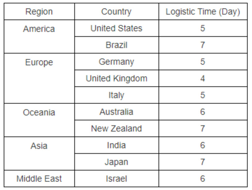
FedEx International, 5-7 business days.
The following are some common countries' logistic time.
Payment Method
| The fee is charged according to the rule of PayPal. | |
| East West Bank charge US$30.00 banking fee. | |
| The fee is charged according to the rule of PayPal. | |
| Western Union charge US$0.00 banking fee. |
Shipping
| DHL(www.dhl.com) From $40.00 basic shipping fee depend on zone and country. |
|
| UPS(www.ups.com) From $40.00 basic shipping fee depend on zone and country. |
|
| FedEx(www.fedex.com) From $40.00 basic shipping fee depend on zone and country. |
|
| Registered Mail(www.singpost.com) From $10.00 basic shipping fee depend on different zone and country. |
Package
|
|
|
|
|
|
VSC7514XKS
technical specifications, attributes, parameters and parts with similar specifications to VSC7514XKS.
Hot Sales in Thermal
Parts with Similar Specs
The three parts on the right have similar specifications to Aavid.
-
ImagePart NameManufacturerHK JDW NOPackageStockDataSheet:Compare:
-
Analog Devices Inc.84-ADG2128BCPZ-REEL732-VFQFN Exposed Pad, CSP2-3 DaysAdd Compare
-
Microchip Technology536-MT8816AF144-TQFP2-3 DaysAdd Compare
-
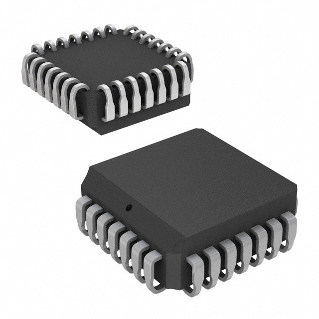
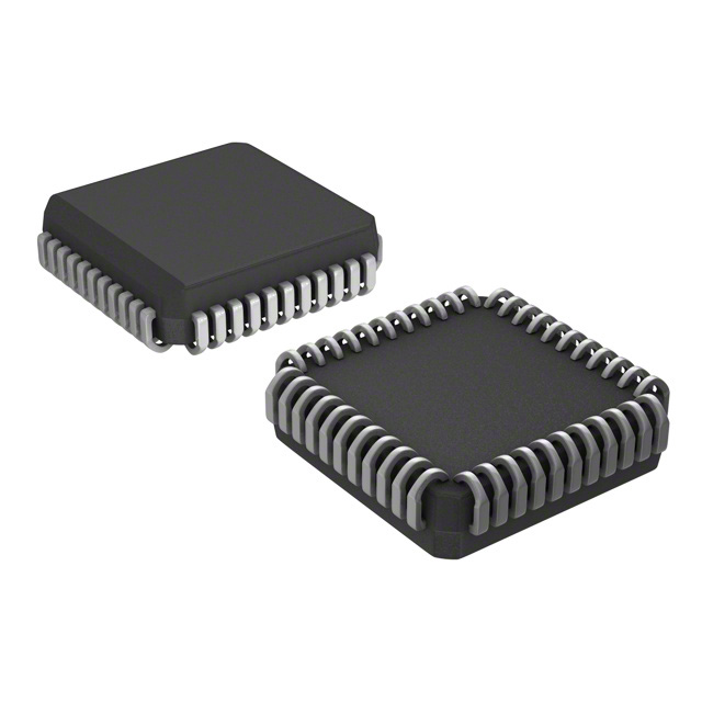
Microchip Technology536-MT8806AP128-LCC (J-Lead)2-3 DaysAdd Compare
-
Microchip Technology536-MT8816APR144-LCC (J-Lead)2-3 DaysAdd Compare
-
Microchip Technology536-MT8812AP144-LCC2-3 DaysAdd Compare
-
Microchip Technology536-VSC7513XKS256-BGA2-3 DaysAdd Compare
-
Microchip Technology536-VSC3308YKU69-LBGA, FCBGA2-3 Days-Add Compare
-
ON Semiconductor598-FSA2269TSUMX10-UFQFN2-3 DaysAdd Compare
-
Microchip Technology536-VSC7390XHO596-BGA2-3 DaysAdd Compare
-
ON Semiconductor598-FSA2268TUMX10-UFQFN2-3 DaysAdd Compare
-
ON Semiconductor598-FSA2567MPX16-WFQFN Exposed Pad2-3 DaysAdd Compare
-
Texas Instruments815-TS3USB221DRCR10-VFDFN Exposed Pad2-3 DaysAdd Compare
-
ON Semiconductor598-FSA2567UMX16-UFQFN2-3 DaysAdd Compare
-
Microchip Technology536-MT8816AP144-LCC (J-Lead)2-3 DaysAdd Compare
-
Microchip Technology536-MT8808AP128-LCC (J-Lead)2-3 DaysAdd Compare
-
Microchip Technology536-HV2601FG-G48-LQFP2-3 DaysAdd Compare
-
ON Semiconductor598-FSAV330MTCX16-TSSOP (0.173, 4.40mm Width)2-3 DaysAdd Compare
-
ON Semiconductor598-FSA2268UMX10-UFQFN2-3 DaysAdd Compare
-
ON Semiconductor598-FSA2269L10X10-UFQFN Exposed Pad2-3 DaysAdd Compare
-
ON Semiconductor598-FSA2269UMX10-UFQFN2-3 DaysAdd Compare





 Need Help?


